


Innovation
Attachment 1: Description of the Function Principle and Product Parameters of the "Three-Proof Valve" for Water Metering
Introduction to the Principle of 'Three-proof Valve'
The first Proof: Preventing Water Meter Self-rotation
Resolving water usage disputes and improving overall customer satisfaction.

The operational principle and process of the three-proof valve (principle: hydraulic self-acting dynamic check valve)
When the user is using water normally, the pressure P2 behind the valve decreases, or various factors may cause the pipeline pressure P1 to rise.
At this time, when the pressure difference: △P = P1 - (P2 + magnetic force) > 0:
a) The separable magnetic valve disc opens rapidly (the degree of opening depends on the water usage, i.e., the size of △P), and the water meter begins to measure.
b) When the user stops using water, or the pressure fluctuation in front of the valve stops or decreases, △P gradually decreases until △P ≤ 0. During this process, relying on magnetism, the separable magnetic valve disc slowly or quickly returns to its seat, achieving a new hydraulic balance (the speed of valve disc return depends on the speed of △P change).
c) In some extreme or special water usage situations, △P changes unusually frequently, often cyclically trending ≥ 0 or ≤ 0. In this case, relying on magnetism, the separable magnetic valve disc is in a "pulsating" working state (opening and closing alternately) until a new pressure balance is reached (it may be fleeting or may last for a short time).
d) If there is an airbag inside the pipe after the meter, the airbag is initially in a gradually compressed state, P1 - P2 = △P > 0. When the airbag is further compressed to a certain extent, it generates sufficient reverse force.
At this time: △P = P2 (mainly due to the reverse force generated by the expansion of the airbag) + magnetic force - valve front pressure P1 > 0. With the further expansion of the airbag, the reverse check force of the valve is greatly enhanced: △P > 0, and the valve is in a fully closed state.
e) The structure of the water meter core determines that the forward measurement value is greater than the reverse measurement value. "Self-rotation" is caused by the repeated accumulation of forward and reverse water flow in front and behind the water meter, which eventually leads to the cumulative reading of the forward direction. The pressure in front of the pipeline cannot rise indefinitely (water supply pressure or secondary water supply pressure values are controlled). Through the repetitions, dynamic equilibrium is reached, and the water meter no longer "self-rotates."
Conclusion:
The water pressure P2 behind the water meter + the magnetic force of the upper and lower magnetic valve discs + the self-weight of the valve disc diaphragm (which can be neglected) - the water pressure P1 in front of the water meter = △P. When you add the high sensitivity of the separable magnetic valve disc to pressure fluctuations, you get hydraulic self-acting dynamic check valve.
Notes:
The magnetic force is approximately 15 to 20 grams, meaning that the pressure difference △P in front and behind the valve should be greater than 15 to 20 grams to open the sealed valve disc. This preload pressure not only ensures the water meter's capacity to measure small amounts of water (the principle of which will be detailed in later chapters) but also minimizes head loss.
The self-weight of the magnetic upper and lower valve discs can be neglected: special composite high-molecular-weight materials are used to generate buoyancy, and the total self-weight of the magnetic valve disc material is approximately 0.
The latest technological upgrade of the product eliminates the diaphragm with channels shown in the schematic diagram and the general type of spring (further reducing water loss).
The second Proof: Addressing the Challenge of "Running, Leaking, and Dripping," Which Hinders Water Meter Measurement or Makes It Difficult
Resolving Water Meter Measurement Sensitivity, Improving Measurement Accuracy, and Ensuring Fairness
Basic Principles and Operation:
a) When there is dripping water behind the meter, the water pressure P2 behind the three-way valve gradually decreases.
b) As time passes with dripping water, the pressure difference between the valve's inlet and outlet, △P = P1 - P2, gradually increases.
c) Once the pressure difference △P exceeds the magnetic force, which is approximately 15-20 grams, the separable magnetic valve disc at the bottom quickly opens. Water from the valve's inlet rapidly flows into the outlet, and the water flow that balances the pressure difference instantly acts on the water meter's impeller. This flow rate is much higher than the water meter's starting flow rate, and the water meter begins measuring.
d) When this water flow passes through the water meter, the hydraulic pressure difference △P before and after the valve becomes zero. Relying on the reverse magnetic force, the separable magnetic valve disc quickly returns to its seat, achieving a new hydraulic balance.
e) Throughout the entire process of dripping water, these phenomena repeat themselves, allowing the water meter to continuously measure the amount of dripping water.
The third Proof: Preventing Backflow of Sewage and Hot Water in Water Systems
Addressing the Risk of Water Pollution and Enhancing Drinking Water Safety

Basic Principles:
The specific function of the check valve sealing force (hydraulic self-acting check) is detailed in the preceding sections on "anti-rotation" and "drip water metering."
The three-proof valve features a sensitive separated valve disc structure, and with the uniform sensitivity of magnetic force between the magnetic valve discs, the three-proof valve exhibits excellent check valve sealing performance. When sewage flows backward, it serves as a barrier.
Conclusion:
Due to the pulsating repulsion effect between the magnetic valve discs' permanent magnets inside the three-proof valve chamber, this repulsion force primarily serves as a rapid and sensitive auxiliary return force and, to a lesser extent, as the initial check valve force.
Therefore, in practical applications, the common issues associated with traditional spring-loaded check valves (which mainly rely on spring-generated check forces), such as insufficient sensitivity, uneven circumferential stress, spring force degradation, and impurities causing blockages, do not occur with the three-proof valve, preventing the widespread phenomenon of gradual malfunction.
Product Basic Dimensional Parameters
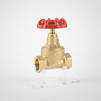
1. Δ Lockable Dynamic Management Three-proof Valve C-Type / Handwheel Dynamic Management Three-proof Valve D-Type Basic Parameters (Channel Type)

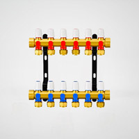
2. ΔHand wheel dynamic management three-proof valve O type

Attachment 1: Description of the Function Principle and Product Parameters of the "Three-Proof Valve" for Water Metering
Introduction to the Principle of 'Three-proof Valve'
The first Proof: Preventing Water Meter Self-rotation
Resolving water usage disputes and improving overall customer satisfaction.
The operational principle and process of the three-proof valve (principle: hydraulic self-acting dynamic check valve)
When the user is using water normally, the pressure P2 behind the valve decreases, or various factors may cause the pipeline pressure P1 to rise.
At this time, when the pressure difference: △P = P1 - (P2 + magnetic force) > 0:
a) The separable magnetic valve disc opens rapidly (the degree of opening depends on the water usage, i.e., the size of △P), and the water meter begins to measure.
b) When the user stops using water, or the pressure fluctuation in front of the valve stops or decreases, △P gradually decreases until △P ≤ 0. During this process, relying on magnetism, the separable magnetic valve disc slowly or quickly returns to its seat, achieving a new hydraulic balance (the speed of valve disc return depends on the speed of △P change).
c) In some extreme or special water usage situations, △P changes unusually frequently, often cyclically trending ≥ 0 or ≤ 0. In this case, relying on magnetism, the separable magnetic valve disc is in a "pulsating" working state (opening and closing alternately) until a new pressure balance is reached (it may be fleeting or may last for a short time).
d) If there is an airbag inside the pipe after the meter, the airbag is initially in a gradually compressed state, P1 - P2 = △P > 0. When the airbag is further compressed to a certain extent, it generates sufficient reverse force.
At this time: △P = P2 (mainly due to the reverse force generated by the expansion of the airbag) + magnetic force - valve front pressure P1 > 0. With the further expansion of the airbag, the reverse check force of the valve is greatly enhanced: △P > 0, and the valve is in a fully closed state.
e) The structure of the water meter core determines that the forward measurement value is greater than the reverse measurement value. "Self-rotation" is caused by the repeated accumulation of forward and reverse water flow in front and behind the water meter, which eventually leads to the cumulative reading of the forward direction. The pressure in front of the pipeline cannot rise indefinitely (water supply pressure or secondary water supply pressure values are controlled). Through the repetitions, dynamic equilibrium is reached, and the water meter no longer "self-rotates."
Conclusion:
The water pressure P2 behind the water meter + the magnetic force of the upper and lower magnetic valve discs + the self-weight of the valve disc diaphragm (which can be neglected) - the water pressure P1 in front of the water meter = △P. When you add the high sensitivity of the separable magnetic valve disc to pressure fluctuations, you get hydraulic self-acting dynamic check valve.
Notes:
The magnetic force is approximately 15 to 20 grams, meaning that the pressure difference △P in front and behind the valve should be greater than 15 to 20 grams to open the sealed valve disc. This preload pressure not only ensures the water meter's capacity to measure small amounts of water (the principle of which will be detailed in later chapters) but also minimizes head loss.
The self-weight of the magnetic upper and lower valve discs can be neglected: special composite high-molecular-weight materials are used to generate buoyancy, and the total self-weight of the magnetic valve disc material is approximately 0.
The latest technological upgrade of the product eliminates the diaphragm with channels shown in the schematic diagram and the general type of spring (further reducing water loss).
The second Proof: Addressing the Challenge of "Running, Leaking, and Dripping," Which Hinders Water Meter Measurement or Makes It Difficult
Resolving Water Meter Measurement Sensitivity, Improving Measurement Accuracy, and Ensuring Fairness
Basic Principles and Operation:
a) When there is dripping water behind the meter, the water pressure P2 behind the three-way valve gradually decreases.
b) As time passes with dripping water, the pressure difference between the valve's inlet and outlet, △P = P1 - P2, gradually increases.
c) Once the pressure difference △P exceeds the magnetic force, which is approximately 15-20 grams, the separable magnetic valve disc at the bottom quickly opens. Water from the valve's inlet rapidly flows into the outlet, and the water flow that balances the pressure difference instantly acts on the water meter's impeller. This flow rate is much higher than the water meter's starting flow rate, and the water meter begins measuring.
d) When this water flow passes through the water meter, the hydraulic pressure difference △P before and after the valve becomes zero. Relying on the reverse magnetic force, the separable magnetic valve disc quickly returns to its seat, achieving a new hydraulic balance.
e) Throughout the entire process of dripping water, these phenomena repeat themselves, allowing the water meter to continuously measure the amount of dripping water.
The third Proof: Preventing Backflow of Sewage and Hot Water in Water Systems
Addressing the Risk of Water Pollution and Enhancing Drinking Water Safety
Basic Principles:
The specific function of the check valve sealing force (hydraulic self-acting check) is detailed in the preceding sections on "anti-rotation" and "drip water metering."
The three-proof valve features a sensitive separated valve disc structure, and with the uniform sensitivity of magnetic force between the magnetic valve discs, the three-proof valve exhibits excellent check valve sealing performance. When sewage flows backward, it serves as a barrier.
Conclusion:
Due to the pulsating repulsion effect between the magnetic valve discs' permanent magnets inside the three-proof valve chamber, this repulsion force primarily serves as a rapid and sensitive auxiliary return force and, to a lesser extent, as the initial check valve force.
Therefore, in practical applications, the common issues associated with traditional spring-loaded check valves (which mainly rely on spring-generated check forces), such as insufficient sensitivity, uneven circumferential stress, spring force degradation, and impurities causing blockages, do not occur with the three-proof valve, preventing the widespread phenomenon of gradual malfunction.
Product Basic Dimensional Parameters
1. Δ Lockable Dynamic Management Three-proof Valve C-Type / Handwheel Dynamic Management Three-proof Valve D-Type Basic Parameters (Channel Type)
2. ΔHand wheel dynamic management three-proof valve O type
